OneRNG - Theory of operation
Change list
- 14 may 2015 - added ent values from new algorithm
- 12 Apr 2015 - correct cmdW to cmdw
- 14 Dec 2014 - Added included initial dieharder results
- 18 May 2014 - Included test analysis from 'ent'
- 22 Feb 2014 - Created
Entropy, noise and random numbers
Modern computers need a source of entropy to seed their random number generators - entropy is simply 'randomness' - for example on a Unix/Linux computer random numbers are available from /dev/random, the kernel generates small amounts of entropy into its entropy pool which feeds the random number generator, if applications empty out the pool they will have to slow down and wait until more entropy is available. Programs that use lots of randomness, for example crypto creating lots of SSL certs will perform poorly.

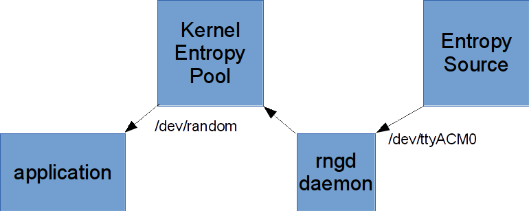
On a Linux machine we can extract our entropy from our device by simply reading from the terminal interface that is created when it's plugged in and writing that data into the kernel entropy pool - the rngd system daemon will do that for us.
Our generator makes random streams of bytes - they're generated by random quantum processes and/or thermal noise - they're don't however present a perfectly randomly distributed bit stream - we get worst case about 7.8 bits of entropy per byte of data presented - it is recommended that you use our generator to feed your kernel random number generator's entropy pool rather than using the data directly. The installation instructions show you how.
Noise Sources
Our entropy generator includes two noise sources, you can choose to use either or both.
The primary noise generator is an avalanche diode (actually a pair of transistors) - it generates a series of random pulses at a frequency faster than we are sampling - we've tweaked the sampling level so that we sample a 1 or 0 roughly 50% of the time - because components are never exactly the same each device will be slightly different, some will sample slightly more 1s than others.
We've measured that our circuit samples slightly more 1s than 0s (about 5% more) - this corresponds to ~7bits/byte of entropy - we could make something with more finely tuned parts, but that would require having someone tweak the circuit on the assembly line, it would likely end up costing twice the price, or more for minimal gain.
The secondary noise generator is an RF receiver built into the CC2531 - it randomly (in time and frequency) skips around channels in and around the 2.4GHz wifi band measuring RF signal levels and sampling just the least significant bit - the CC25xx system document has some analysis of the use of this technique you can look at - we're measuring a very slight bias (0.14% more 1s than 0s). This performance is better than the avalanche diode circuit, but RF is by definition theoretically more susceptible to outside manipulation.
The default setting has the primary (avalanche diode) noise source enabled, and the secondary (RF source) disabled
Whitening
Because our byte streams have the minor built in sampling biases mentioned above it's useful to be able to pass them through a 'whitening' stage - a process that mixes up the bits to even out the number of 1s and 0s without reducing the amount of entropy present in the byte stream. Some applications like rngd check for bitstream sanity and will complain if there are too many more ones or zeros - whitening helps them accept our bitstream and feed it to the kernel random number generator.
In our case we have a CRC16 generator to use for whitening, when it's enabled we push each byte into the generator and extract the upper byte of the running CRC sum - this means that the bits of adjacent bytes are merged and xored together evening out the number of ones and zeros. This operation can be turned on or off, by default it's turned on. If you want the raw data turn it off.
Putting it all Together
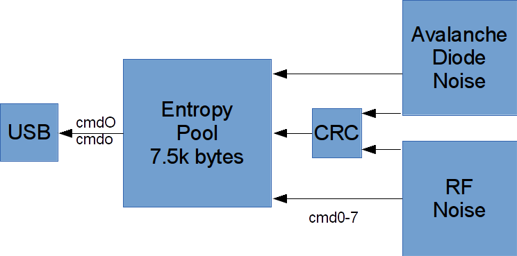
Internally most of the device's RAM is used as an entropy pool:

Data is sourced a byte at a time from the two noise sources, if both are enabled alternate bytes are taken from each one, if the whitener is turned on the byte is passed through it.
The entropy pool works as a FIFO until it is full, subsequent data is continually xored into the pool as a ring buffer - this means that the entropy/byte value approaches 8 bits/byte if the pool is sampled at a lower rate than the rate at which it is filled.
.
When data is copied from the entropy pool to the USB controller it is cleared.
Crypto
The CC2531 has AES support, we don't use it in the system firmware - but if want to you're welcome to use it - sample code is available in the base Cheap RF kernel (RF and crypto support has been removed from the version of the OS used here but can be easily added back in).
Command and Control
The basic interface to the device is a simple terminal interface - commands are written to the device, entropy data is returned. All commands are ascii, 4 bytes the first 3 of are always "cmd" (always lower case) followed by a single letter command, any other data is ignored.
There are only a small number of commands:
- 'O' (upper case-O) "on" starts the entropy feed from the internal buffer to the USB interface (by default at system startup it is off)
- 'o' (lower case-O) "off" - turns the USB feed off
- 'w' flushes the entropy buffer
- '0'-'9', 'a'-'f', 'A'-'F' mode - a single hex digit encoding 4 bits, the most significant bit is undefined (so values greater than '7' are undefined and should not at be used) valid combinations are:
| Value | Avalanche
Disable | RF
Enable | Whitener
Disable | Function |
| cmd0 | 0 | 0 | 0 | Avalanche noise with whitener (default) |
| cmd1 | 0 | 0 | 1 | Raw avalanche noise |
| cmd2 | 0 | 1 | 0 | Avalanche noise and RF noise with whitener |
| cmd3 | 0 | 1 | 1 | Raw avalanche noise and RF noise |
| cmd4 | 1 | 0 | 0 | No noise |
| cmd5 | 1 | 0 | 1 | No noise |
| cmd6 | 1 | 1 | 0 | RF noise with whitener |
| cmd7 | 1 | 1 | 1 | Raw RF noise |
- 'X' this commands dumps out an image of the CPU's code memory - depending on which CPU variant you have you'll either get 256k or 128k - all data fields are little endian:
| Offset | Bytes | Function |
| 0x000000 | 6 | Magic number - frames the data in the data stream 0xFEEDBEEF2014 |
| 0x000006 | 3 | size in bytes |
| 0x000009 | 2 | firmware VERSION |
| 0x00000b | 2 | actual code size |
| 0x00000d | 128k/256k | firmware image |
The actual firmware image is quite small - under 8k - however in order to make sure that imposter code is not present it is padded with random data to the end of flash memory to make it hard to compress and PGP signed.
Measured Performance
'ent' results
We analyzed OneRNG performance in its various modes using the linux 'ent' entropy test program by collecting 100mB worth of data in each mode - our original beta usings (firmware versions 1 or 2) used a simple algorithm for sampling the avalanche data - this resulted in these results:
| Mode | Entropy bits/byte | Arithmetic mean | Chi Square | Monte Carlo value for Pi | Serial Correlation |
| 0 | 7.999998 | 127.5082 | 50% | 3.141540123 | -0.000107 |
| 1 | 7.839684 | 148.7502 | 0.01% | 2.558361194 | 0.000466 |
| 2 | 7.999998 | 127.5036 | 25% | 3.142011216 | 0.000147 |
| 3 | 7.999352 | 128.8613 | 0.01% | 3.107938012 | -0.000299 |
| 6 | 7.999998 | 127.4945 | 25% | 3.141584420 | -0.000044 |
| 7 | 7.999998 | 127.4969 | 90% | 3.141813404 | -0.000096 |
Version 3 firmware (the version shipping to Kickstarter participants) uses a new algorithm that double samples for each bit with some time separation between samples - this results in improved results:
| Mode | Entropy bits/byte | Arithmetic mean | Chi Square | Monte Carlo value for Pi | Serial Correlation |
| 0 | 7.999998 | 127.4896 | 2.5% | 3.141419209 | -0.000117 |
| 1 | 7.967816 | 117.9809 | 0.01% | 3.350023094 | 0.000302 |
Notes:
Entropy: goal is 8 bits/byte
Arithmetic mean: 127.5 is the ideal
Chi Square: values between 10% and 90% are good
Analysis: mode 1 is raw avalanche diode data - we know there's a DC sampling bias here which shows in the arithmetic mean, and other numbers (this offset is a design tradeoff, the alternative is hand tweaking devices on the manufacturing line that would raise costs) - mode 7 is raw RF noise, it's higher quality. Mode 3 is combined (interleaved) data from both generators, as a result it's of an intermediate quality. Modes 0, 2, 4 are whitened versions of modes 1, 3, 5 resp.
The RF noise source makes slightly higher quality noise than the avalanche diode, but it does depend on something external to the device - if you're a bit paranoid we recommend mode 0, otherwise mode 6 or 7 will do well (remember they skip from channel to channel at random intervals which slightly reduces the data rate). We default to mode 0.
Noise Spectrum
Another way of looking at the system is to measure the frequency distribution of the sampled values, looking for interfering signals (in our case for example we might be looking for an interfering signal
from the boost power supply) - here's a plot obtained from Audacity by capturing a 100mB file from the avalanche diode (mode '1') then reading it in as 8-bit signed raw data then plotting the spectrum using a box ("Rectangular Window") filter.

'dieharder' results
dieharder is a well known random number testing program. We plan on running it on a selected group of OneRNG modes - it takes a long time for each run (over a month) so we don't have a large collection yet:
- 'cmd0' - this is the avalance diode with the whitener turned on - this is the default mode the device runs in
Circuit Description
The full schematic is here:

Briefly:

The above circuit fragment is a switching voltage boost converter - it converts 3 volts to around 20 volts to drive the avalanche diode

This circuit fragment consists of two transistors, one biased in an unusual way to form an avalanche junction and the other to help amplify the result, followed by a simple transistor amplifier biased so that it generates a signal that is sampled at roughly 50:50 ones to zeroes by the CC2531's input anti-metastability flops (who's very purpose in life we are sorely testing here - but adding to our entropy in the process).
Links
Back to main page


