All the pins on the Arduino, analog and digital pins can be used as digital inputs - all you need to do is use the "pinMode()" routine, usually in setup(), to configure the pin - for example to make digital pin 2 an input: pinMode(2, INPUT);
Below we'll explain about "pullup resistors" - you can enable a built in pullup resistor on each input with this call:
pinMode(2, INPUT_PULLUP);
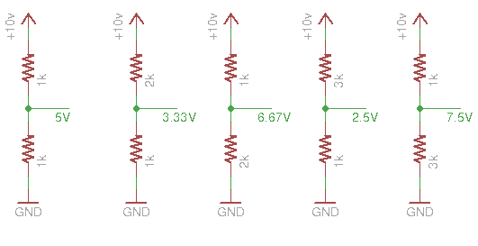
When you connect two resistors together in a row (we say "in series") the voltage in the middle depends on the ratio of the two resisters. We call this a "voltage divider", below are some examples, remember 'GND' means "0 volts". when the resistors are the same the voltage is half - when the resistor ratio is 2:1 you get 1/3 or 2/3 the voltage - when they are 3:1 you get 1/4 or 3/4. The larger the resistor on the bottom the higher the voltage.
A special case of a voltage divider is when there is no resistor - in this case we say the voltage is "pulled up" or "pulled down" and the voltage on the output is the same as the power supply it is connected to:
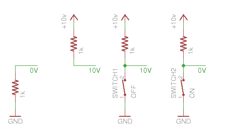
If you connect a pullup to +V and a switch to ground then when the switch is on the midpoint will be 0V and when it's off the midpoint will be +V. As mentioned above Ardinos have built in pullup resistors that can be enabled in software.
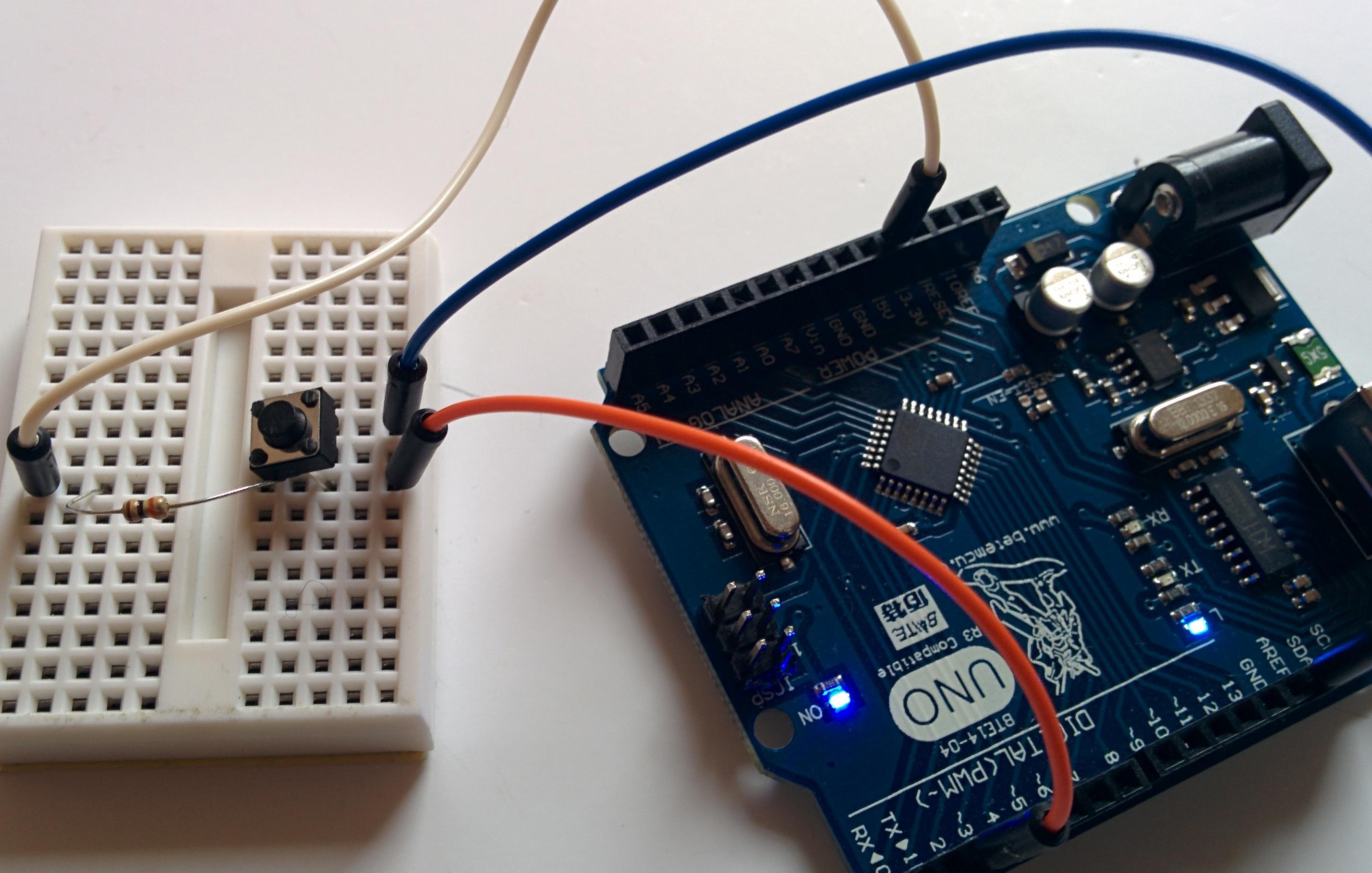
Suppose you hook up a switch and connect it to digital input 2 like this:
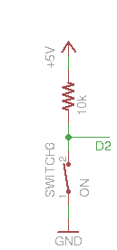
Digital inputs don't measure voltages directly , just "on" or "off", or "1" or "0". "On" or "1" is an input voltage close to 5V, "off" or "0" is a voltage near 0V. You should avoid applying voltages that are not near 0 or 5V to a digital input, you can damage the CPU.
You read the state of a digital input like digital pin 2 using: digitalRead(2), and if you connect an LED to pin 3 - for example:
	void setup() {
  		pinMode(2, INPUT);
  		pinMode(3, OUTPUT);
	}

	void loop() {
		int val = digitalRead(2);
		if (val == LOW) {
			digitalWrite(3, HIGH);
		} else {
			digitalWrite(3, LOW);
		}
	}
Then you now have a switch for an LED - remember that when the switch is pressed the input is LOW and we must set the LED on when it's high.
You can toggle the LED on and off every time you press the switch by remembering the previous state of the switch and the state of the LED.
	int last_switch = HIGH;
	int led_state = LOW;
	void setup() {
  		pinMode(2, INPUT);
  		pinMode(3, OUTPUT);
		digitalWrite(3, LOW);
	}

	void loop() {
		int val = digitalRead(2);
		if (val == LOW && last_switch == HIGH) {	// a button was just pressed
			if (led_state == LOW) {			// change the LED state
				led_state = HIGH;		// 	to what it isn't
			} else {
				led_state = LOW;
			}
			digitalWrite(3, led_state);		// set the LED
		}
		last_switch = val;				// remember the last switch value
	}
Only some pins can be analog inputs - the A0-A7 pins along one side - they can be used to measure a voltage they return a value between 0 and 1023 every time they are read - analogRead(3) returns the current voltage on pin 3 - these units are 1/1024ths of the supply voltage (5V - about 0.0049v)
Many sensors that read more than on or off work by creating a voltage divider with one resistor replaced by a sensor which acts like a resistor - you pick a matching resistoir that has a value about the same as the sensor.
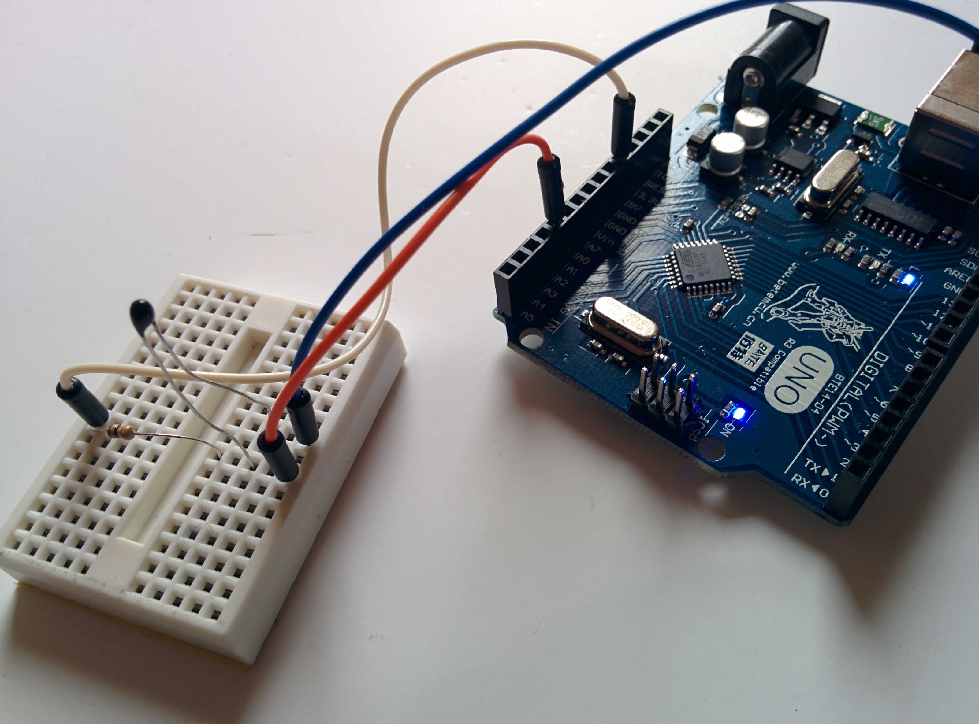
A "thermistor" is a device who's resistance changes as its temperature changes - you can put it in a circuit like this:
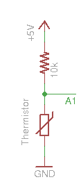
And read it with "analogRead(1)" [for pin A1] - but what do the values mean? it depends pn the device, we don't have data sheets for our thermistors but we can measure them. Here's a simple program, that reads A1 and prints out its value every second:
	void setup() {
		Serial.begin(9600);
  		pinMode(A1, INPUT);
	}

	void loop() {
		Serial.println(analogRead(A1));
		delay(1000);
	}
To see this output open the serial monitor using Tools->Serial Monitor in the Arduino build system. Try holding the bulb of the thermistor with your fingers to warm it up and see the values change
With a thermometer you can build a table of temperatures and measured value to calibrate your thermistor.
This program turns on an LED when the temperature gets too high:
	void setup() {
  		pinMode(3, OUTPUT);
	}

	void loop() {
		int v = analogRead(A1);
		if (v < 220) {
			digitalWrite(3, HIGH);		// set the LED if the temp is too high
		} else {
			digitalWrite(3, LOW);		// off the LED if the temp is low
		}
	}
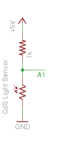
Also in the kit is a Cadmium Sulphide (CdS) light sensor, you can use it in a voltage divider with a 1k resistor:
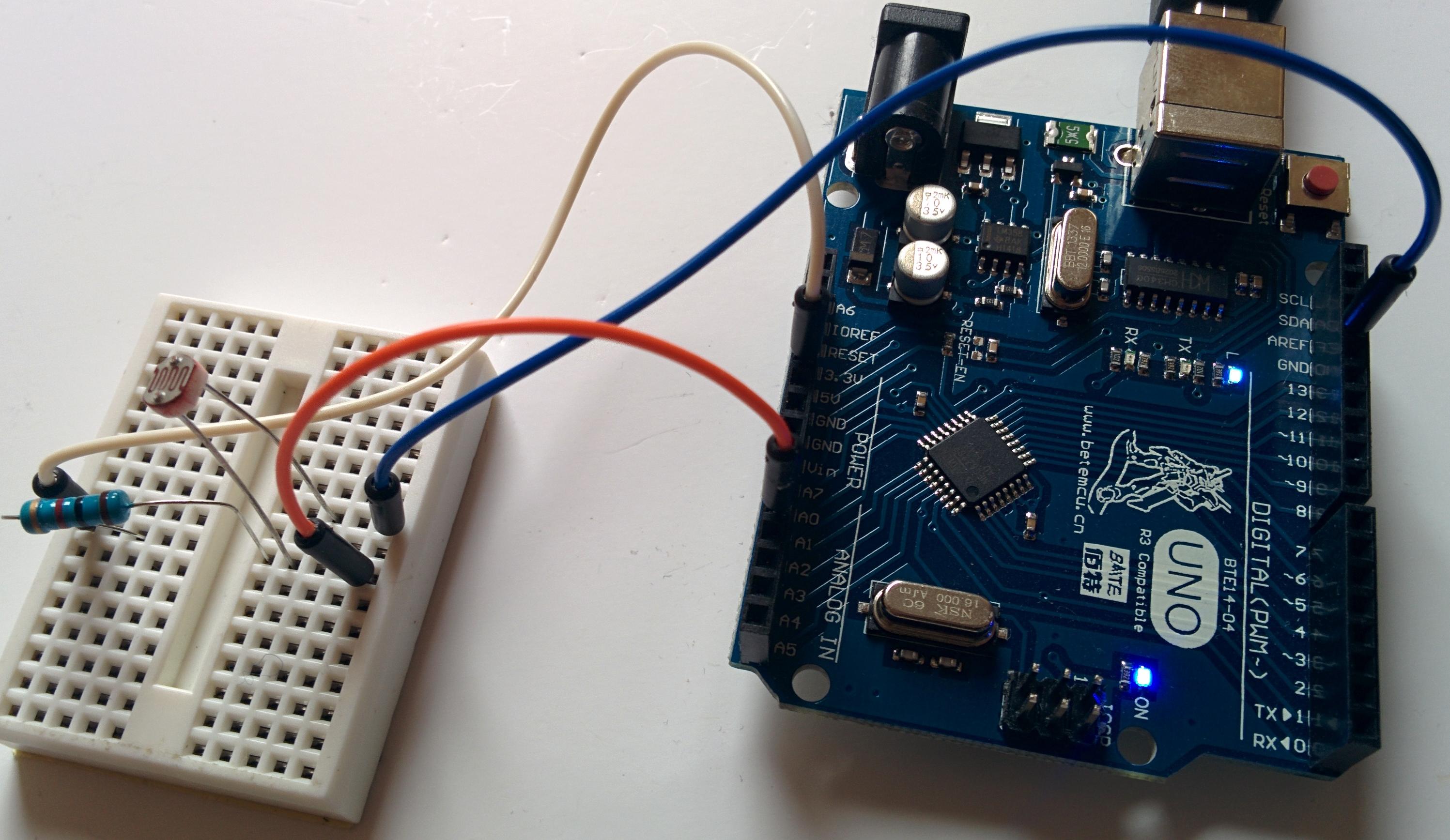
Try the program that prints out analog values above, shading the sensor with your hand should change the values printed.
Can you make a program that turns on an LED when it gets dark? what happens if you point the sensor at the LED?