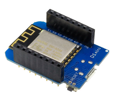
The WeMOS D1 CPU you have is a 'clone', a cheap copy, of a real D1 - the circuits are different but they program the same.
The actual CPU is inside the rectangular metal box in the middle. The button at the side is the "reset" button, it stops the CPU and tells it to start again at the beginning. The wiggly line at the top is the wifi antenna.
There is 1 light (LED) it flashes to tell you when the D1 is talking to the USB connector when you are loading programs into it, you can also turn it on and off from your programs.
On both sides of the CPU are black connectors for "pins" - these are how you connect your D1 to other circuits to make them do things. Or you can plug in another circuit board on top called a "shield". Your D1 came without the black connectors, we soldered some on for you, there are extra connectors that you don't need but might be useful later. Each pin is labeled:
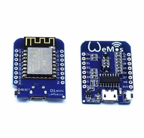
The pins labelled D0-D8 are digital input or output pins, it's best to use them starting from D8 downwards. Digital pins can be outputs: they can either be turned "on" (have 3.3 volts on them), or "off" (have 0 volts on them - ie ground/GND). Or they can be inputs, can sense an "on" (close to 3.3V) or "off" (close to 0 volts) on them.
Pin A0 is for analog inputs. We can use it to measure a voltage between 0 and 1 volt as a number. Pin G is the only ground pin, 3V3 is the 3.3volts power supply. We can use them to power our circuits.
The extra pins - RST, TXD, RXD and especially 5V are best not used at the beginning. The D1 is a 3.3V part, it can be damaged if you use 5 volts around it.
You can find more information about the pins and a full scematic here
If you haven't read the "Getting Started" section and installed the Arduino software now's the time to go and do it
So let's write a little program. Arduino programs are called "sketches" there's already an example sketch called "Blink: you can find from the "File" menu - choose "Examples"->"01.Basics"->"Blink". It looks something like this:
	// the setup routine runs once when you press reset:
	void setup() {
  		// initialize the digital pin as an output.
  		pinMode(LED_BUILTIN, OUTPUT);
	}

	// the loop routine runs over and over again forever:
	void loop() {
  		digitalWrite(LED_BUILTIN, HIGH);   // turn the LED on (HIGH is the voltage level)
  		delay(1000);               // wait for a second
  		digitalWrite(LED_BUILTIN, LOW);    // turn the LED off by making the voltage LOW
  		delay(1000);               // wait for a second
	}
Load your sketch into your D1 - press the right arrow "upload" icon at the top of the page - you'll see the LED on the D1 twinkle. Once the new program has been loaded it will automatically run - the LED on the board will now flash. The D1 will always remember the last program you have loaded into it, even after you have turned it off.
The delay() in the program makes the CPU wait - how long is measured in milliseconds - one thousandth of a second - to make it flash faster change the two "1000"s to "100". Now load your change sketch into your D1 - he LED on the board will now flash faster. You've loaded a new program into your D1.
When you load a program into an Arduino or D1 the computer remembers the program, even if you turn the power off
Notice how every Arduino sketch has two parts that must always be there:
Firstly "setup()" is called once when the Arduino starts a sketch - which is when the D1 is turned on, the reset button is pressed, or a new program is loaded. This is where you put the code that only has to be called once to set the system up, things like choosing what a particular pin will do.
  	void setup() {
                // initialisation stuff goes here
        }
Secondly "loop()" is called over and over again as fast as possible after setup() has been called - this is where you put the code that will actually do things.
  	void loop() {
                // most of your program goes here
        }
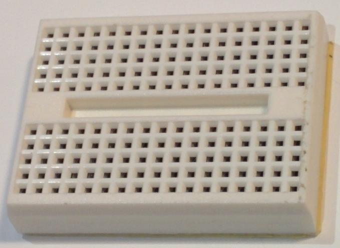
Prototyping boards are used for easily connecting wires and components together without solder - the one in your kit is a very simple one - it has rows of 5 holes - any wire or component pushed into a hole in a row will be connected to any other component pushed into another hole in the same row.
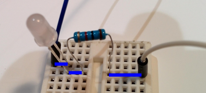
For example the black, green and blue lines on this diagram show rows of holes that are connected:
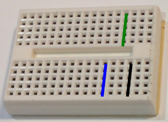
Be gentle with your proto boards - pushing wires or components with leads that are too big, more than one wire per hole, or forcing things into them can damage them and make them not work as well. You may find that trimming
Let's make something simple - connect an LED and a 470 ohm (yellow-purple-brown or yellow-purple-black-black) resistor between the "3.3V" and "G" - first take a resistor and an LED and a couple of hookup wires and plug them into your proto board like this (look closely at which row each pin goes into):
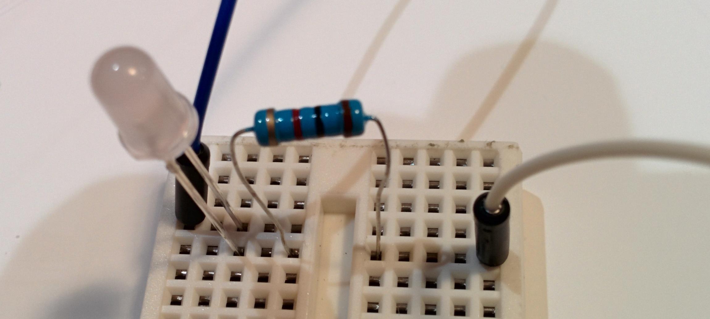
Really they are wired together like this:
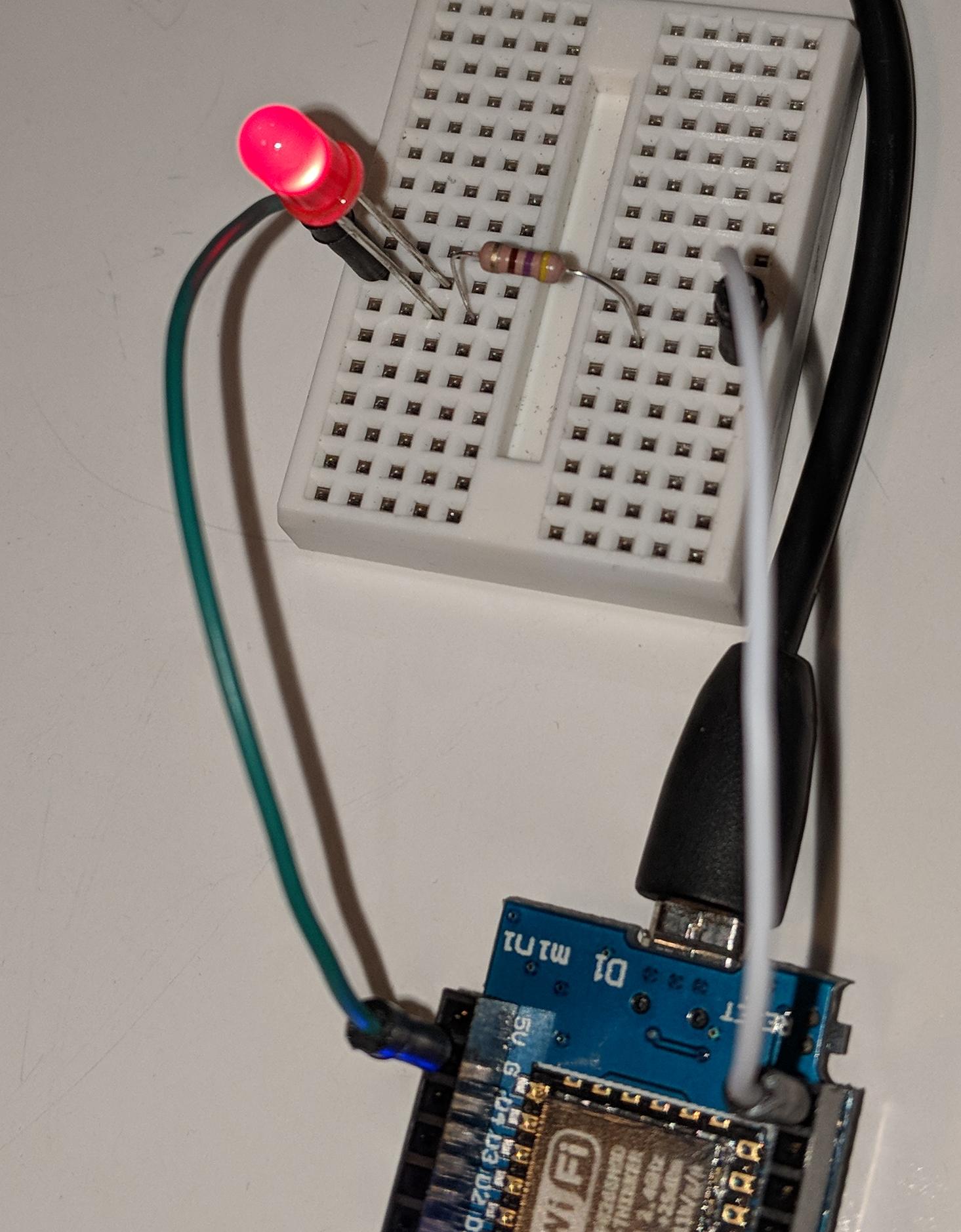
Now hook one of the wires to "3.3v" pin on your D1 and the "G" pin. If the LED doesn't light switch the pins, or turn the LED around.
Some kits have a different type of prototyping board similar to the one shown below on the left:
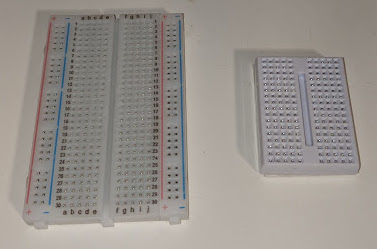
The middle parts of these boards work the same as the smaller one, the outer two rows on either side are connected the length of the board, by convention the blue one is used for ground
Because the D1 has only one G (ground/GND) pin it's a good idea to connect that pin to a row on the proto board and then connect other ground connections to there
When you plug your D1 into a computer it's powered over the computer's USB, once you've loaded a program into it you don't need to keep powering it from the computer, instead you can supply external power to the 5V pin - anything up to about 9V can practically be used - 6V (4 batteries) is a great choice.
Alternately there are a number of shields available to add rechargeable batteries, coin cells, external power adaptors, etc - try following the link below
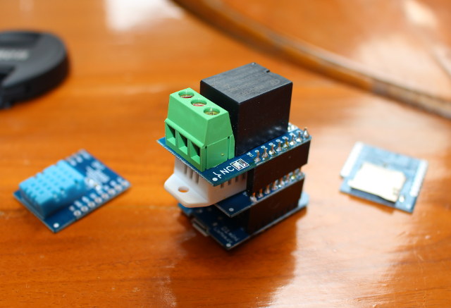
"shields" are small circuit boards that can be plugged into the two black connectors on top of the D1 - there are many different sorts available - Aliexpress has many different sorts (there are lots of other places to buy them as well).
If you've built a cool circuit on your proto board and want something a bit more permanent that won't fall apart when you move it you can also buy D1 prototyping boards to solder components onto they cost ~50c each, Paul has a few to give away free, if you want one please get in touch and see if there are any left